📘
MIA6513112:モータードライブ

Motor drive for robot sanding unit
| MirkaCode: | MIA6513112 |
| EANCode: | 6416868743791 |
Motor drive for Mirka® AIROS
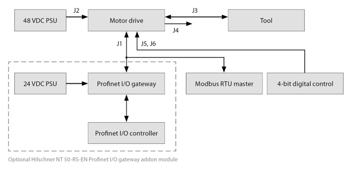
General
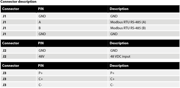
- Connect the 48 VDC power supply to the motor drive (J2 connector).
- Connect the tool to the motor drive (J3 connector).
Modbus RTU interface
- Use the J1 connector to connect the motor drive to the Modbus RTU bus.
Profinet I/O gateway to Modbus RTU interface
- Connect the 24 VDC power supply to the gateway and connect the DSUB-9 adapter cable between the gateway (X2 connector) and the motor drive (J1 connector).
Digital control interface
- Use the J6 connector to connect the common GND between the systems.
- Use the J5 connector to select the operation using the four digital input signals.
Relay interface
- The N/O relay pins are available on the J4 connector.
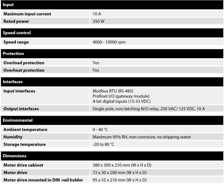

The motor drive PCB comes mounted in a DIN-rail holder that can be attached to a standard 35 x 7.5mm EN50022 DIN-rail, but the motor drive PCB can be removed from this holder and mounted using the mounting holes instead.
If the mounting holes are used, then it is recommended to use 20 mm metal standoffs and 10 mm M3 screws when mounting the motor drive PCB.
It is recommended to use 10 mm ferrules with plastic sleeve for each wire that is attached to any of the connectors.
The wires can then easily be pushed into the connectors and released with the help of a small flat-head screwdriver (3.5 mm blade width, 0.6 mm blade thickness).
NOTE! NTC– and P– are connected together to the same PIN inside the connector.
Hilscher NT 50-RS-EN adapter cable pinout (female DSUB-9)
Modbus RTU
Modbus RTU over RS-485 is used to communicate with the motor drive.
The motor drive is configured as a Modbus RTU slave device and the default slave address is 86. The slave address can be changed if it conflicts with another Modbus RTU slave device.
The J1 connector on the motor drive is used for ModbusRTU communication.
A shielded twisted pair cable is recommended and the shield should be earthed only at one point, normally at the master device.
The A-pin of the J1 connector is equivalent to RxD / TxD+ and the B-pin is equivalent to RxD / TxD–.
RS-485 configuration
Basic operation for Modbus RTU
The motor drive must be in ON-state before the tool can be started.
The very first command that should be sent to the motor drive is the ON-state command.
It is not mandatory to send the OFF-state command before removing power from the motor drive.
When the motor drive is in ON-state the speed set-point value can be written and the state can be set to RUN-state by sending the RUN-state command.
This will cause the tool to run at the set-point speed.
To stop the tool, set the motor drive to STOP-state by sending the STOP-state command.
It is recommended to continuously monitor the average speed,average current,tool temperature,motor drive temperature and the alarm status flag.
This will help to detect if there are any issues present during operation.
Example sequence for starting and stopping the tool:
- Write 4 (0x0004) to the “Operation” register, this will set the motor drive to ON-state.
- Write 4000 (0x0FA0) to the “Speed set-point” register, this will set the set-point speed to 4,000 rpm.
- Write 1 (0x0001) to the “Operation” register, this will set the motor drive to RUN-state and the tool will start running.
- Write 2 (0x0002) to the “Operation” register, this will set the motor drive to STOP-state and the tool will stop running.
- Write 8 (0x0008) to the “Operation” register, this will set the motor drive to OFF-state.
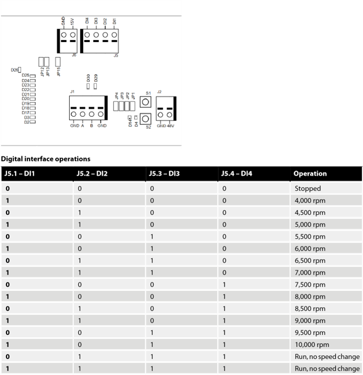
Digital interface
The motor drive can also be controlled via the digital interface instead of Modbus RTU, but with the added drawback that there is no feedback when using the digital interface.
To enable the digital interface, the JP12 jumper needs to be set.
Connector J5 is used as input for the digital interface.
The input is considered high if a voltage between 15–33 VDC is applied to the input pin.
The input is considered low if the voltage is below 12 VDC or if the input is left floating.
The GND pin of connector J6 must be connected between the systems.
The J6 connector can also be used to provide a 15 VDC control voltage if needed.
Self-test function
While holding down the S1 button the motor drive will perform a quick self-test.
The alarm status flag will be set to 6 (self-test running).
The indicators D4 and D14 will blink green if temperatures and voltages are within the limits.
If the temperatures or voltages are not within the limits then the indicators will blink red.
Reset function
The reset button S2 can be pressed momentarily to reset the motor drive.
This is essentially the same as turning the power off and on again.
Factory reset function
The configuration stored in the motor drive can be reset to factory defaults if needed.
This will restore the factory assigned Modbus slave address and the last known tool configuration will be reset to factory defaults.
Follow these steps to do a factory reset:
- Set jumper JP15.
- Press and hold S2 for 5 seconds.
- Remove JP15.
Write protection
The holding registers for “Device name” and “Slave address” are normally read-only to prevent accidental writes to these registers.
If any of these registers needs to be changed, follow these steps:
- Write 64 (0x0040) to “Operation” register to disable the write protection.
- Write the new value to “Device name” or “Slave address” holding registers.
- Write 128 (0x0080) to “Operation” register to enable the write protection.
Safety stop / E-Stop
モータードライブ自体には、外部安全停止/E-Stop信号を検出したり反応したりするための入力はありません。
ツールケーブルのA、B、C相を接続または切断するために、モータドライブの近くに適切なコンタクタを使用することができます
The motor drive itself does not have any inputs for detecting or reacting to an external safety stop / E-Stop signal.
A suitable contactor can be used placed near the motor drive to connect or disconnect the tool cable phase A, B and C wires.
On the fly tool change function
Multiple tools can be used with the same motor drive but only one tool can be connected to the motor drive at any given time.
When changing from one tool to the next, follow these steps:
- Stop the tool by writing 2 (0x0002) to the “Operation” register.
- Write 16 (0x0010) to the “Operation” register to let the motor drive know that you are intending to disconnect the currently attached tool.
- Wait 1 second before disconnecting the currently attached tool from the motor drive.
- Disconnect the currently attached tool from the motor drive.
- Connect the next tool to the motor drive.
- Write 32 (0x0020) to the ”Operation” register to let the motor drive know that the new tool has been attached.
- Wait 1 second before starting the new tool.
Protection features
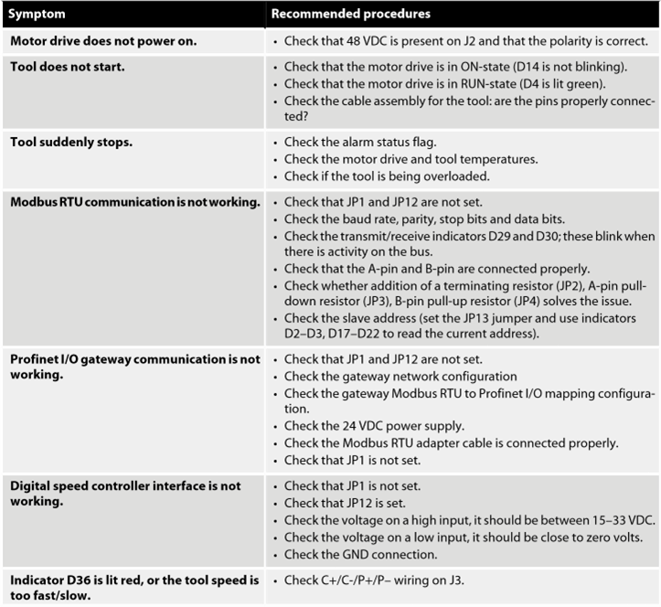
Troubleshooting guide